This one is a decision tree, not a report. Every node below is a fork I actually stood at, what I picked, and what I killed. Most of the interesting parts of this project were things the model told me confidently that turned out to be wrong.
Back to Projects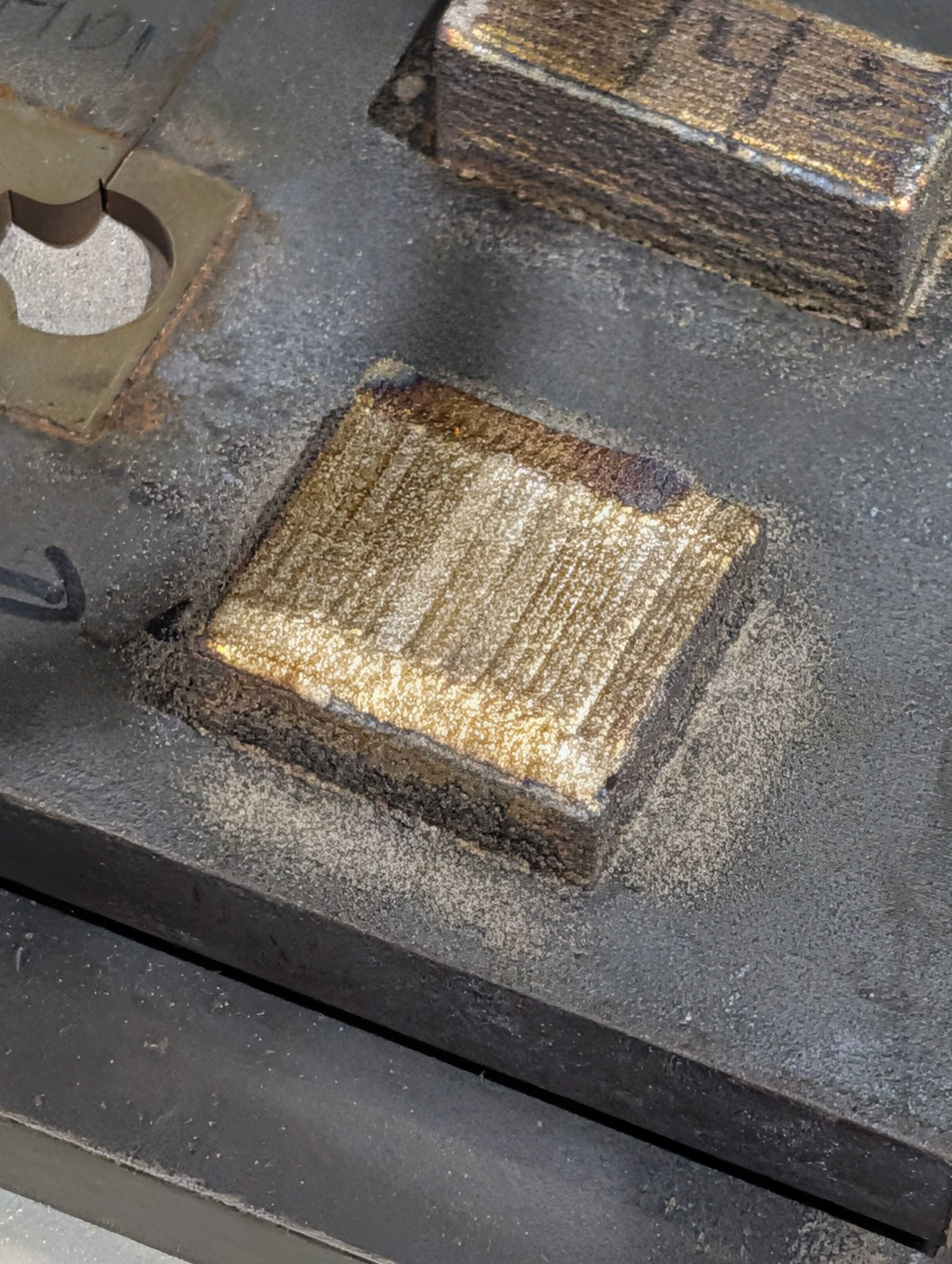
CHARPAGNE LAB | BIMETALLIC STEEL SIMULATION
Simulation Engineering InternJun 2026 - Present
Explicit DynamicsFEAParametric StudyAdditive ManufacturingDesign of Experiments
"This one is a decision tree, not a report. Every node below is a fork I actually stood at, what I picked, and what I killed. Most of the interesting parts of this project were things the model told me confidently that turned out to be wrong."
Engineering Deep Dive
Print a soft steel and a hard steel into the same part and the composite beats both. 316L stretches to about 42 percent but gives up early on strength. PH17-4 is nearly twice as strong and snaps at 8 percent. Held inside the 316L, that same PH17-4 has been measured reaching roughly 60 percent strain, because the soft phase physically stops it necking when it wants to.
My job was to build that in Ansys and find out whether the effect survives when you change the layout.
Implicit is the obvious default for a slow tensile pull. I went explicit instead. Necking is an instability, and an implicit solver has to iterate to equilibrium at exactly the moment equilibrium stops existing. Explicit marches forward in tiny steps and never has to converge, so it walks straight through the neck.
The cost of that choice shows up immediately in the next node.
Explicit solvers are built for crashes. To finish a run in reasonable time you have to pull the specimen far faster than any real machine would, which quietly turns a static problem into a dynamic one.
I ran the same specimen at 50, 25, 5 and 0.5 m/s and tracked kinetic energy against internal energy. At 50 m/s the specimen fractured at the grip radius instead of mid gauge. That is not a material result. That is a stress wave arriving at a geometric discontinuity before the rest of the bar has noticed it is being pulled. The solution crossed into quasi-static behaviour somewhere between 5 and 25 m/s, so I settled at 5 m/s, where kinetic energy stays under 5 percent of internal energy.
Ran 5, 2, 1.5 and 1 mm in the gauge region. Peak stress moved 0.5 percent between 2 mm and 1 mm, so 2 mm was the answer. Refining past that buys nothing and costs everything, because element size sets the solver timestep and I was working inside a 32,000 element student license.
The model was returning a peak stress far below anything structural steel can do, alongside energy error terminations and elements reporting negative density.
I went hunting in the wrong places first. Mesh quality came back fine at a minimum element quality of 0.857, which ruled it out. The actual cause was one field on the stock material card: it was set to a shock equation of state, meant for genuine impact problems, and its presence silently disabled automatic mass scaling across the entire model. Not for that body. For everything. One inherited setting on one material was invalidating every run in the project.
A second setting was compounding it. The minimum timestep floor had been left at 1e-4 s against a natural timestep near 9e-8 s, so the solver was adding enormous artificial mass to hold that floor.
Writing custom cards with a linear equation of state, and dropping the floor to 1e-8 s, made the numbers physical again. This is the most useful thing I learned all summer and it is invisible in every plot I produced.
The composite kept failing at 10 to 12 percent strain with none of the confined necking the experiments show. It looked like a real fracture result.
It was not. My hardening curve only had data out to about 4.4 percent plastic strain, and past the last point the solver holds the curve flat. Stress pinned at exactly 1003 MPa, the last value in the table. A flat hardening curve violates the Considere condition, which is the criterion that says a material can only keep deforming uniformly while it is getting stronger faster than it is getting thinner. With zero slope, the first element to yield takes all the strain and runs away.
The tell was in my own output: max plastic strain jumped from 0.040 to 0.232 in a single timestep, exactly at the plateau. The tempting fix was to raise the failure threshold and make the symptom go away. That would have buried the bug and kept every number wrong.
Then the harder question. I had been telling the solver to delete an element once it passed a fixed strain or stress value. But the entire point of this material is that confinement lets the hard phase survive far past the strain it could reach on its own, roughly 60 percent against 8 percent unconfined. A single fixed number cannot represent a failure point that the surrounding geometry is actively pushing further out.
So the criterion came off entirely, as a diagnostic baseline rather than a fix. Doing that also exposed a separate conflict where the hard-phase threshold was deleting reinforcement elements before they ever carried load. The direction it points is a triaxiality-dependent description, where lateral constraint from the soft phase raises hydrostatic stress and suppresses the instability, rather than a hand-tuned cutoff.
I was reading reaction force at the end I was pulling. Wrong end. That face is where the loading wave is launched, so it reads the wave before it reads the specimen, and the early part of the curve rings badly enough to be unusable.
The fixed support reads the load that actually made it through the gauge. I also dropped the habit of charting maximum stress against maximum strain, because the element carrying peak stress and the element carrying peak strain are not the same element at any given timestep, so that curve describes no physical point in the specimen.
Then I froze the method as a one line protocol and applied it identically to all 25 runs, so the sweep would at least be internally consistent.
The real question is whether the composite cares about how much hard phase there is, or how it is arranged.
So I built 25 specimens: five reinforcement counts crossed with five volume fractions, in a dogbone scaled from the ASTM E8 subsize reference by a factor of 1.75. Gauge cross section held fixed at 10.5 by 3 mm, fiber height fixed at 1 mm, fiber width solved per cell, and the leftover width split into equal segments.
The tightest case leaves 0.44 mm between fibers, close to a single deposition bead. Worth knowing before anyone tries to print it.
The two steels differ in stiffness by about 1 percent, so almost nothing partitions elastically. Everything interesting happens after yield, when 316L saturates near 403 MPa while PH17-4 climbs past 701. That gap is the whole mechanism, and it is what the partitioning plots are built to show.
Ran a 25 case parametric sweep mapping stiffness, yield strength and elongation against reinforcement count and volume fraction.
Traced a model-wide instability to a single equation of state setting on an inherited material card that was silently disabling mass scaling, plus a timestep floor set four orders of magnitude above the natural timestep.
Established mesh convergence at 2 mm and quasi-static validity at 5 m/s, both against documented Ansys criteria rather than by feel.
Correctly diagnosed premature failure as a truncated hardening curve rather than a fracture event, and refused the fix that would have hidden it.
Rebuilt the load and strain extraction method after finding the original probe location was reading the loading wave.
Audited the machine G-code for the specimen and found a feedrate parameter that was assigned but never referenced, making an intended speed override do nothing.
Calibrating a Johnson-Cook failure model needs three tests spanning tension, shear and compression. Cyclic load-unload-reload data would let me model back stress properly instead of assuming isotropic hardening. And the layout space is barely touched: brick and mortar, Bouligand and crossed-lamellar architectures all exist in the literature and none of them have been run here.
CONTACT
Let's Build Something Great
I'm currently working at Tesla, but I'm excited about the possibilities for the upcoming summer! Whether you have a question about my work or want to discuss a project, my inbox is open.